Transfer case — removal and installation
1. Disconnect the cable from the negative terminal of the battery (see Battery — disconnection and reconnection).
2. On models with a manually shifted trans- fer case, put the transfer case in the 2WD High position.
3. Raise the vehicle and support it securely on jack stands.
4. Remove the stone shields (skid plates), if equipped.
5. Drain the transfer case lubricant (see Tune-up and routine maintenance).
6. Remove the front and rear driveshafts (see Driveline).
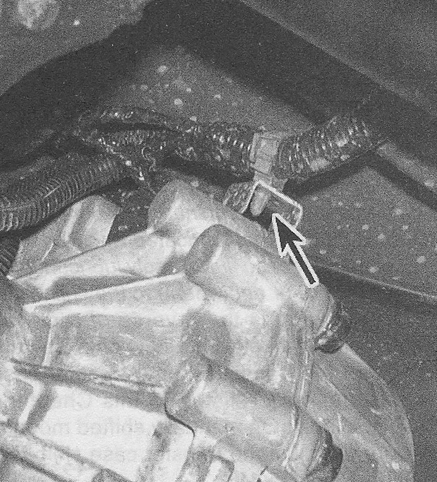
7. Unplug all electrical connectors and detach the vent hose from the top of the transfer case (see illustration). If necessary, disconnect the transfer case vent tube.
10.7 Detach the wiring harness retaining clips and vent hose from the transfer case

8. On manually shifted models, disconnect the shift linkage from the transfer case. This is done by simply pulling the shift linkage ball socket off the ball pivot on the transfer case shift lever.
9. Raise the transmission enough to remove the crossmember (see Automatic transmission). With the crossmember removed, support the transmission with a floor jack.
10. If necessary, remove the transmission mount from the transmission (see Transmission mount — check and replacement).
11. Support the transfer case with a jack — preferably a special jack made for this purpose. Safety chains will help steady the transfer case on the jack.
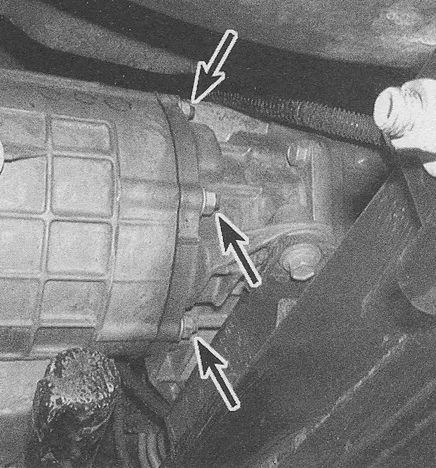
12. Remove the transfer case adapter-to transmission mounting nuts. On some models, the fuel line bracket may be attached by the mounting nuts (see illustration).
10.12 Remove the transfer case adapter- to-transmission mounting nuts

13. Make a final check that all wires and hoses have been disconnected from the transfer case, then move the transfer case and jack toward the rear of the vehicle until it’s clear of the transmission. Keep the transfer case level as this is done. Once the input shaft is clear, rotate the transfer case as necessary, lower it and remove it from under the vehicle.
14. Remove the adapter-to-transfer case bolts and remove the adapter as needed.
Note: Before installation of the transfer case and adapter to the transmission, on transmission/transfer case combinations where the input shaft is «dry» (not lubricated with transmission or transfer case fluid), apply lubricant (GM P/N 12345879 or equivalent) to the splines.
15. Installation is the reverse of removal. Replace the gasket with a new one. Be sure to tighten the transmission-to-transfer case nuts to the torque listed in this Chapter’s Specifications. On manually shifted models, be sure to adjust the transfer case shift linkage (see Shift linkage (manual-shift models) — replacement and adjustment).