Oxygen sensors — general information and replacement
General information
1. An oxygen sensor is a galvanic battery that produces a very small voltage output in response to the amount of oxygen in the exhaust gases. This voltage signal is the input side of the feedback loop between the oxygen sensor and the Powertrain Control Module (PCM). Without it, the PCM would be unable to correct the injector on-time (which determines the air/fuel ratio) to maintain the perfect (known as stoichiometric) air/fuel ratio of 14.7:1 that the catalyst needs for optimal operation.
2. All vehicles covered by this manual have On-Board Diagnostics II (OBD-II) engine management systems, which means they have the ability to monitor the performance of the catalytic converter. They accomplish this by using an oxygen sensor ahead of the catalytic converter and another oxygen sensor behind the catalytic converter. By comparing the amount of oxygen in the post-catalyst exhaust gas to the oxygen content of the exhaust gas before it enters the catalyst, the PCM can determine the efficiency of the converter.
3. All models covered by this manual have four heated oxygen sensors: one upstream sensor (ahead of the catalytic converter) per cylinder bank and one downstream sensor (after the catalytic converter) per cylinder bank. The upstream sensors are located on the upper part of the front exhaust pipe assembly, above the catalytic converters. The downstream sensors are located under the vehicle, in the exhaust pipes, just behind the catalytic converters.
4. The upstream and downstream oxygen sensors are heated to speed up the warm-up time during which the sensors are unable to produce an accurate voltage signal. The circuit for each oxygen sensor heater is controlled by the PCM, which opens the ground side of the circuit to shut off the heater as soon as the sensor reaches its normal operating temperature.
5. Special cares must be taken whenever a sensor is serviced.
a) Oxygen sensors have a permanently attached pigtail and an electrical connector that cannot be removed. Damaging or removing the pigtail or electrical connector will render the sensor useless.
b) Keep grease, dirt and other contaminants away from the electrical connector and the louvered end of the sensor.
c) Do not use cleaning solvents of any kind on an oxygen sensor.
d) Oxygen sensors are extremely delicate. Do not drop a sensor, throw it around or handle it roughly.
e) Make sure that the silicone boot on the sensor is installed in the correct position. Otherwise, the boot might melt and it might prevent the sensor from operating correctly.
Replacement
Note: Because they’re installed in the exhaust pipes, which contract as they cool down, the oxygen sensors can be very difficult to loosen when the engine is cold. Rather than risk damage to a sensor or its mounting threads, start and run the engine for a minute or two, then shut it off. Be careful not to burn yourself during the following procedure.
Upstream oxygen sensor
Note: The upstream oxygen sensors are located on the upper part of the front exhaust pipe assembly, just above the catalytic converters.
6. Raise the vehicle and place it securely on jack stands.
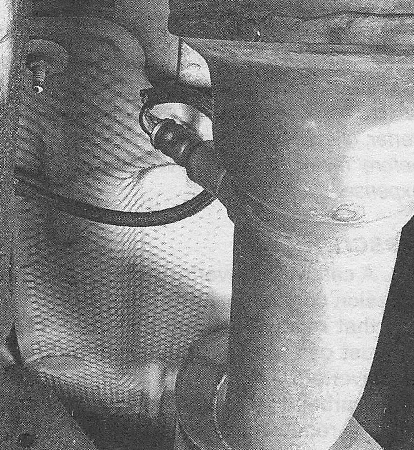
7. Locate the oxygen sensor (see illustrations), then trace the sensor electrical lead to the electrical connector and disconnect the connector.
11.7a Left upstream oxygen sensor (bank 1, sensor 1) location, viewed from underneath the vehicle, looking forward (V6 model shown, V8 models similar)

11.7b Right upstream oxygen sensor (bank 2, sensor 1) location, viewed from the right wheel well, with the splash shield removed (V6 model shown, V8 models similar)

8. Using an oxygen sensor socket (available at most auto parts stores), unscrew the upstream oxygen sensor (see illustration). If the sensor is difficult to loosen, spray some penetrating oil onto the sensor threads and allow it to soak in for a while.
11.8 Using an oxygen sensor socket, unscrew the upstream oxygen sensor from the exhaust manifold (right upstream sensor shown)

9. If you’re going to install the old sensor, apply anti-seize compound to the threads of the sensor to facilitate future removal. If you’re going to install a new oxygen sensor, it’s not necessary to apply anti-seize compound to the threads. The threads on new sensors already have anti-seize compound on them.
10. Installation is otherwise the reverse of removal. Be sure to tighten the sensor to the torque listed in this Chapter’s Specifications.
Downstream oxygen sensor
Note: The downstream oxygen sensors are located on top of the exhaust pipes, just behind the catalytic converters.
11. Raise the vehicle and place it securely on jack stands.
12. Locate the downstream oxygen sensor (see illustrations), then trace the sensor electrical lead to the connector and disconnect it.
11.12a Left-side downstream oxygen sensor (bank 1, sensor 2)

11.12b Right-side downstream oxygen sensor (bank 2, sensor 2)

13. Unscrew the downstream oxygen sensor with an oxygen sensor socket (see illustration 11.8). If the sensor is difficult to loosen, spray some penetrating oil onto the sensor threads and allow it to soak in for a while.
14. If you’re going to install the old sensor, apply anti-seize compound to the threads of the sensor to facilitate future removal. If you’re going to install a new oxygen sensor, it’s not necessary to apply anti-seize compound to the threads. The threads on new sensors already have anti-seize compound on them.
15. Installation is otherwise the reverse of removal. Be sure to tighten the sensor to the torque listed in this Chapter’s Specifications