Lower control arm — removal and installation
Removal
1. Loosen the wheel lug nuts, raise the vehicle and support it securely on jack stands placed under the frame rails. Remove the wheel.
2. Disconnect the stabilizer bar link from the control arm (see Stabilizer bar, bushings and links (front) — removal and installation).
3. Remove the shock absorber lower mounting fasteners (see Shock absorber (front) — removal and installation).
4. On 4WD models, remove the drive axle (see Driveline).
5. If you’re working on a model with torsion bar front suspension, remove the torsion bar (see Torsion bar — removal and installation).
6. Using rope or wire, support the upper control arm and steering knuckle from the top of the shock absorber.
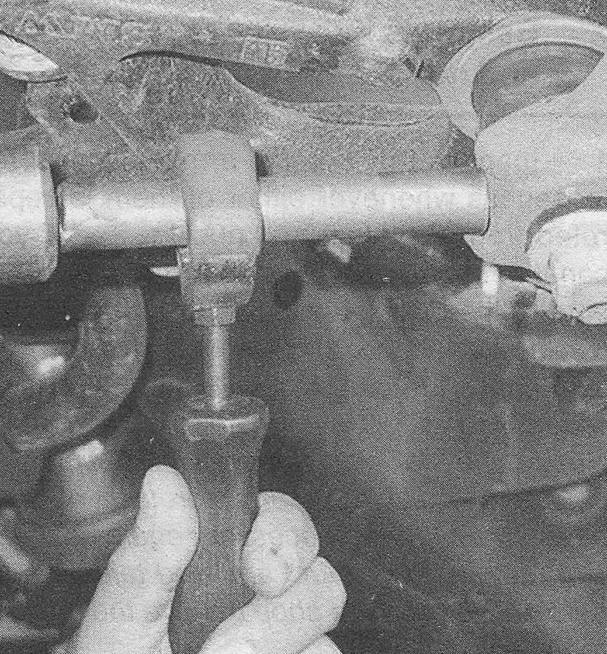
7. To disconnect the lower control arm from the steering knuckle, loosen the ball joint nut a few turns (don’t remove it), install a ball joint separator and break the ball joint loose from the knuckle (see illustration). Now remove the nut.
6.7 A drift and a hammer can be used to loosen the ball stud from the steering knuckle if a ball joint separator isn’t readily available

Note: If you don’t have the proper ball joint removal tool, a hammer and a drift can sometimes be used to break the ball stud loose from the knuckle. A pickle fork-type ball joint separator can also be used, but keep in mind that this type of tool will probably damage the ball joint boot.
Note: The manufacturer recommends replacing the ball joint nut with a new one whenever it has been removed.
8. Remove the lower control arm pivot bolts and nuts (see illustration), noting which way the bolts are installed. Pull the lower arm from its frame brackets.
6.8 Lower control arm pivot bolts (1500 model)

Installation
9. Position the arm in the frame brackets and install the bolts and nuts, but don’t tighten them yet.
10. Attach the ballpoint to the steering knuckle, install a new nut and tighten it to the torque listed in this Chapter’s Specifications.
11. The remainder of installation is the reverse of removal. Be sure to tighten all fasteners to the torque values listed in this Chapter’s Specifications.
Note: The pivot bolt nuts should be tightened with the vehicle at normal ride height. This can be done after the vehicle has been lowered to the ground (on vehicles with adequate clearance), or it can be simulated by raising the lower control arm with a floor jack.
12. Install the wheel and lug nuts. Lower the vehicle and tighten the lug nuts to the torque listed in the Tune-up and routine maintenance Specifications.
13. If you’re working on a model with torsion bar front suspension, be sure to check and adjust the ride height (see Torsion bar — removal and installation).
14. Have the front-end alignment checked and, if necessary, adjusted.