Cylinder heads — removal and installation
Warning: Wait until the engine is completely cool before beginning this procedure.
Note: It will be necessary to purchase a new set of 11 mm cylinder head bolts for this procedure.
Removal
1. Relieve the fuel system pressure (see Fuel and exhaust systems). Disconnect the cable from the negative terminal of the battery (see Engine electrical systems) and drain the cooling system (see Tune-up and routine maintenance).
2. Remove the intake manifold (see Intake manifold and Valve Lifter Oil Manifold (VLOM) — removal and installation).
3. On 5.3L and 6.2L engines, remove the fuel rail (s) from the cylinder head(s) (see Fuel and exhaust systems).
4. Detach the exhaust manifold (s) from the cylinder head(s) (see Exhaust manifolds — removal and installation). It is not necessary to disconnect the manifold(s) from the exhaust pipe(s).
5. Remove the valve cover (s) (see Valve covers — removal and installation).
6. Remove the rocker arms and pushrods (see Rocker arms and pushrods — removal, inspection and installation).
Caution: Again, as mentioned in Section Rocker arms and pushrods — removal, inspection and installation, keep all the parts in order so they can be reinstalled in the same locations.
7. Remove the coolant air bleed pipe.
Left cylinder head
8. Remove the alternator and its bracket (see Engine electrical systems) (see illustration).
9.8 The alternator bracket can be unbolted and moved forward as a complete assembly — 6.0L model shown

9. Disconnect the ground strap at the back of the cylinder head.
Right cylinder head
10. On 6.0L models, remove the dipstick tube.
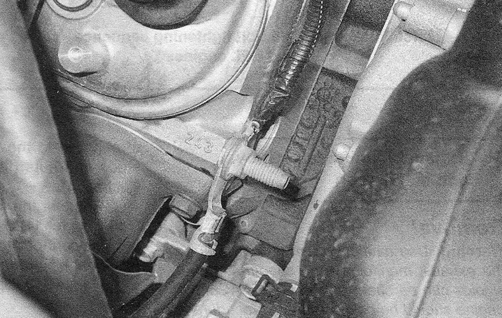
11. Disconnect the ground cables from the front of the cylinder head (see illustration).
9.11 Label, then disconnect the ground wires that are bolted to the right cylinder head

Both cylinder heads
12. Loosen the head bolts in 1/4-turn increments in the reverse order of the tightening sequence (see illustration 9.22a or 9.22b) until they can be removed by hand.
Note: There will be different length and size head bolts for different locations. Make a note of the different sizes and lengths and where they go when removing the bolts to ensure correct installation of the new bolts.
13. Lift the head (s) off the engine. If resistance is felt, do not pry between the head and block as damage to the mating surfaces will result. To dislodge the head, place a pry bar or long screwdriver into the intake port and carefully pry the head off the engine (see illustration).
9.13 Using a prybar inserted into an intake port to break the head loose — do not use excessive force or damage to the head may result

14. Store the heads on blocks of wood to prevent damage to the gasket sealing surfaces.
Installation
15. The mating surfaces of the cylinder heads and block must be perfectly clean when the heads are installed. Gasket removal solvents are available at auto parts stores and may prove helpful.
16. Use a gasket scraper to remove all traces of carbon and old gasket material, then wipe the mating surfaces with a cloth saturated with brake system cleaner. If there is oil on the mating surfaces when the heads are installed, the gaskets may not seal correctly and leaks may develop. When working on the block, use a vacuum cleaner to remove any debris that falls into the cylinders.
Note: The cylinder heads on some engines are made of aluminum; therefore, aggressive scraping is not suggested and will damage the sealing surfaces.
17. Check the block and head mating surfaces for nicks, deep scratches and other damage. If damage is slight, it can be removed with emery cloth. If it is excessive, machining may be the only alternative.
18. Use a tap of the correct size to chase the threads in the head bolt holes in the block. If a tap is not available, spray a liberal amount of brake cleaner into each hole. Use compressed air (if available) to remove the debris from the holes. All cylinder head bolts should be replaced with new bolts.
Warning: Wear safety glasses or a face shield to protect your eyes when using compressed air.
19. Position the new gaskets over the dowels in the block (see illustration).
9.19 Position the head gasket over the dowels at each end of the cylinder head with the mark facing the front of the vehicle

20. Carefully position the heads on the block without disturbing the gaskets.
21. Before installing the 8mm head bolts, coat the threads with a medium-strength thread locking compound. Then install the new 8mm head bolts (bolts 11 through 15).
22. Install new 11 mm head bolts (bolts 1 through 10) and tighten them finger tight. Following the recommended sequence (see illustrations), tighten the bolts in four steps to the torque listed in this Chapter’s Specifications.
9.22a Cylinder head bolt tightening sequence — 5.3L and 6.2L engines

9.22b Cylinder head bolt tightening sequence — 6.0L engine

Caution: DO NOT reuse head bolts – always replace them with new ones.
23. Install the coolant pipe, using new gaskets, onto the cylinder heads. Tighten the bolts to the torque listed in this Chapter’s Specifications.
24. The remainder of installation is the reverse of removal.
25. Add coolant and change the oil and filter (see Tune-up and routine maintenance). Start the engine and check for proper operation and coolant or oil leaks.